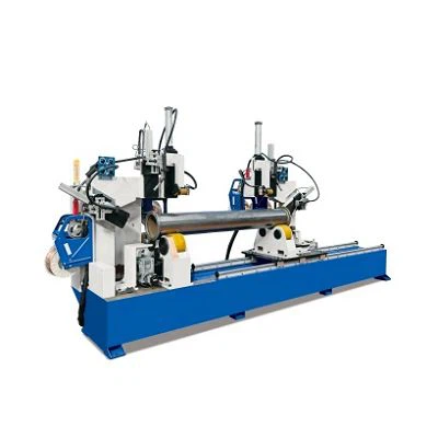
In commercial vehicle, heavy machinery, and automotive manufacturing, the fuel tank is a critical safety component requiring 100% leak-proof integrity, high structural strength, and flawless aesthetic finish. As global manufacturing shifts toward automation, manual welding often becomes a bottleneck due to inconsistent seam quality, high labor costs, and slow production speed.Investing in an automatic fuel tank welding machine is a strategic decision that directly impacts your production line's throughput and ROI. However, with various welding processes (MIG/MAG, TIG, Laser) and machine configurations (longitudinal, circumferential, 5-axis CNC, robotic workstations) available, choosing the right system can be complex.This comprehensive guide breaks down the core technical factors, welding processes, and selection criteria to help plant managers and procurement engineers make an informed decision.

1. Identify Your Fuel Tank Specifications & Material Properties
Before evaluating equipment features, define the exact technical parameters of your target workpieces:
1.Tank Material: Aluminum alloy (5052/6061) is widely used for heavy truck tanks due to lightweighting, whereas stainless steel or carbon steel is common for specialized industrial tanks. Aluminum demands precise heat input control and stable AC TIG or Pulse MIG power sources.
2.Plate Thickness: Typically ranges from 1.5mm to 3.0mm. Thinner gauge metals risk burn-through during welding, requiring specialized arc tracking and pulsed current controls.
3.Tank Shape & Dimensions: Round, square ,ect require different torch movement systems
2. Compare Core Welding Processes for Fuel Tank Fabrication
Selecting the right power source and welding method determines both joint quality and cycle speed:
|
Welding Process |
Ideal Material & Thickness |
Main Advantages |
Typical Limitations |
|
Pulse MIG/MAG |
Aluminum / Steel ($1.8\text{mm} - 4.0\text{mm}$) |
High welding speed, deep penetration, cost-effective consumables |
Moderate spatter, requires post-weld cleaning |
|
TIG Welding |
Stainless Steel / Thin Aluminum ($\le 2.5\text{mm}$) |
Superior cosmetic finish, zero spatter, maximum leak tightness |
Slower travel speed compared to MIG |
|
Plasma Welding |
Stainless / Carbon Steel ($2.0\text{mm} - 6.0\text{mm}$) |
Single-pass full penetration, low thermal distortion |
Higher initial equipment investment |
|
Laser Welding |
Ultra-thin or high-precision tanks |
Fastest speed, minimal heat-affected zone (HAZ) |
Strict requirement for joint fit-up gap tolerance |
3. Select the Appropriate Machine Configuration Based on Weld Type
The standard fuel tank manufacturing process typically includes three different automated welding stations:
A. Longitudinal Welding (Tank Body)
Longitudinal welds utilize pneumatic keyways for rolling and forming the tank body, ensuring uniform heat dissipation and minimizing thermal deformation during straight weld joints.
B. Double Circumferential Welding (End Caps)
Double-end circumferential welders are equipped with dual welding heads, an electric tailstock, and a synchronous rotation device, enabling simultaneous welding of two end caps. Compared to single-head systems, this reduces the welding cycle time by 50%.
C. Baffle and Joint Installation
Internal anti-sway baffles and external inlet/outlet fuel joints typically require robotic welding workstations with weld tracking sensors to handle complex 3D paths.
4. Key Automation Functions
When consulting with machinery manufacturers for solutions, ensure the equipment includes the following key automation modules:
- Automatic Arc Voltage Control (AVC) / Weld Tracking: Real-time compensation for workpiece dimensional tolerances and thermal expansion ensures a consistent distance between the welding torch and the workpiece.
- PLC + Touchscreen Interface: Supports storing and recalling job parameters for quick program changes between weld seams of different sizes.
- Pneumatic/Hydraulic Fixtures: Achieves precise positioning without manual spot welding, avoiding deformation caused by manual spot welding.
Step-by-Step Selection Workflow for Procurement Engineers
1.Step 1: Define Technical Requirements:Crucial for accurate supplier quotations.
Collect exact tank engineering drawings, material specifications (e.g., Al 5052-H32), thickness tolerances, and daily output requirements (e.g., 120 tanks/shift).
2.Step 2: Request Welding Sample Tests:Validate penetration and seam cosmetics.
Send material samples to the equipment manufacturer for trial welding. Inspect cross-sectional penetration, X-ray leak tightness, and seam appearance.
3.Step 3: Evaluate Fixture & Control System Flexibility:
Verify whether the clamping tooling supports quick adjustments for various tank lengths and cross-sections without extensive downtime.
4.Step 4: Audit After-Sales & Commissioning Support:
Confirm that the manufacturer provides comprehensive site preparation guidelines, overseas installation/commissioning, and rapid spare parts availability.
5.Conclusion: Partnering for Custom Welding Solutions
Choosing the right automatic fuel tank welding machine goes beyond comparing machinery price tags. It requires selecting a custom system tailored to your material grades, production volume, and factory automation goals.
With 22 years of expertise in industrial automation, our engineering team delivers turnkey fuel tank welding production lines-from longitudinal seamers to 5-axis CNC workstations-exported to over 50 countries worldwide.